Subroutines
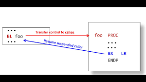
Every programming language has its own term for a subroutine: procedure, function, subprogram, method, routine, etc.
It is interesting to break a large program into smaller separate logical units. It makes the program more modularized and allows to reuse code for a task.
A subroutine is a sequence of instructions. If you want to use it, you jump to it, execute its instructions and jumps back to the place from which it was called.
The subroutine is not allowed to modify the environment (registers) after the jump from the main code (caller address). In order to jump back to the address of the next instruction after the one that started the function, the call address must be saved.
A safe way to write a subroutine is to follow the Procedure Call Standard for the ARM Architecture (AAPCS).
Calling a subroutine
To define a subroutine, begin by using
.type YourFunction, %function”
which ensures that the lowest bit is set (rather than using +1).
Subroutine calls are performed with the BL (branch and link) instruction, which
saves in the Link Register (LR or register r14) the return address of the next instruction following the BL instruction. In Cortex M, this address is PC + 4.
performs a jump. In other words, it loads the program counter (PC) with the memory address of the first instruction of the subroutine.
When the subroutine is executed, it returns to the caller by jumping to the address stored in LR by executing the following instruction:
mov pc, lr ; load program counter (PC or r15) with the return adress stored in the link register (LR or r14).
When calling a subroutine, the BL instruction sets the less significant bit in LR.
Let’s improve our GPIO blinking code by adding two subroutines:
53clockGPIO:
54ldr  r1, =RCC_BASE       //  4002 1000
55ldr  r2, [r1,#AHB2ENR]   //  4002 104c
56orr  r2, #RCC_AHB2ENR_GPIOAEN
57orr  r2, #RCC_AHB2ENR_GPIOBEN
58str  r2, [r1,#AHB2ENR]
59mov  pc,lr
 64config_GPIO:
 65
 66ldr  r1, =GPIOA_BASE        //  4800 0000
 67ldr  r2, [r1,#GPIO_MODER]      // after reset, r2 is 0xabffffff
 68bic  r2, #GPIO_MODER_MODE6_1     // reset bit 1 mode 6  -> "01"    set PA6 to OUTPUT mode  2*6=12
 69bic  r2, #GPIO_MODER_MODE7_1     // reset bit 1 mode 7  -> "01"    set PA6 to OUTPUT mode  2*7=14
 70str  r2, [r1,#GPIO_MODER]
 71
 72ldr  r1, =GPIOB_BASE        //  4800 0400
 73ldr  r2, [r1,#GPIO_MODER]      // after reset, r2 is 0xabffffff
 74bic  r2, #GPIO_MODER_MODE6_1     // reset bit 1 mode 6  -> "01"    set PA6 to OUTPUT mode  2*6=12
 75str  r2, [r1,#GPIO_MODER]
 76
 77// set PUSH-PULL/open-drain mode
 78ldr  r1, =GPIOA_BASE        //  4800 0000
 79ldr  r2, [r1,#GPIO_OTYPER]     // after reset, r2 is 0xabffffff
 80bic  r2, #GPIO_OTYPER_OT6       // 0: output push-pull (reset state)
 81bic  r2, #GPIO_OTYPER_OT7       // 0: output push-pull (reset state)
 82str     r2, [r1,#GPIO_OTYPER]  //  value of PA OTYPE register
 83
 84// set pin speed
 85ldr  r1, =GPIOA_BASE        //  4800 0000
 86ldr  r0, [r1,#GPIO_OSPEEDR]    //  value of PA OSPEED register
 87ldr  r2, = GPIO_OSPEEDR_OSPEED6_0
 88ldr  r3, = GPIO_OSPEEDR_OSPEED6_1   //  10
 89orr  r0, r0, r2
 90orr  r0, r0, r3
 91str     r0, [r1,#GPIO_OSPEEDR]
 92
 93// set "no pull"
 94//  00: No pull-up, pull-down   01: Pull-up   10: Pull-down  11: Reserved
 95ldr  r1, =GPIOA_BASE        //  4800 0000
 96ldr  r2, [r1,#GPIO_PUPDR]      //  value of PUPD register
 97bic  r2, #GPIO_PUPDR_PUPD6_0    // no pull (reset state)
 98str     r2, [r1,#GPIO_PUPDR]
 99
100bx     lr
The main program becomes:
16.text
17
18.type Reset_Handler, %function  // the following is instructions, not data. Thus lsbit of address is set.
19Reset_Handler:
20
21ldr  r0, =0x10101010
22ldr  r1, =0x10203040
23bl clockGPIO           // enable the GPIO A and B clocks via the AHB2ENR register
24bl config_GPIO         // configure GPIO registers
25
26// ---------------------------------------------------------------
27ldr r3, =1000000
28ldr r5, =200000
29
30ldr r1, =GPIOB_BASE        //  4800 0400
31ldr r6, =GPIO_BSRR_BR_6
32ldr r7, =GPIO_BSRR_BS_6
33
34BlinkLoop:
35str     r6, [r1,#GPIO_BSRR]
36
37mov r4, r3
38delay1: subs r4, #1
39bne delay1
40
41str     r7, [r1,#GPIO_BSRR]
42
43mov r4, r5
44delay2: subs r4, #1
45bne delay2
46
47b BlinkLoop
Just before the instruction bl clockGPIO, we have:
lr             0xffffffff          -1
pc             0x8000106           0x8000106 <Reset_Handler+6>
After 5 single steps, we are ready to leave the clockGPIO subroutine:
clockGPIO () at gpio.s:54
54     ldr  r1, =RCC_BASE       //  4002 1000

PC and LR are now
lr             0x800010b           134217995
pc             0x800012e           0x800012e <clockGPIO>
LR memorized the return address 0x 800 0106 + 4 + 1 (bit 0 = 1), or 0x 800 010b
Subroutine last instruction before return
(gdb) s
halted: PC: 0x0800013c
59     mov  pc,lr

lr             0x800010b           134217995
pc             0x800013c           0x800013c <clockGPIO+14>
After returning to the main program
(gdb) s
halted: PC: 0x0800010a
Reset_Handler () at gpio.s:24
24     bl config_GPIO          // configure GPIO registers

lr             0x800010b           134217995
pc             0x800010a           0x800010a <Reset_Handler+10>
The PC register has now the value stored in LR (minus 1; the LSB is reset), so the next instruction will be a jump to the second subroutine.
Subroutine calling another subroutine
Let’s insert a call to config_PIO inside clockGPIO:
53clockGPIO:
54 ldr  r1, =RCC_BASE       //  4002 1000
55 ldr  r2, [r1,#AHB2ENR]   //  4002 104c
56 orr  r2, #RCC_AHB2ENR_GPIOAEN
57 orr  r2, #RCC_AHB2ENR_GPIOBEN
58 str  r2, [r1,#AHB2ENR]
59 bl config_GPIO                // configure GPIO registers
60 mov  pc,lr
Just before the call to config_GPIO; we have
; lr             0x800010b           134217995
; pc             0x800013c           0x800013c <clockGPIO+14>
Let’s single step:
(gdb) s
halted: PC: 0x0800013e
config_GPIO () at gpio.s:66
66     ldr  r1, =GPIOA_BASE        //  4800 0000
Now the LR value has changed:
(gdb) i r lr pc
lr             0x800013d           134218045
pc             0x800013e           0x800013e <config_GPIO>
LR now contains the return address to clockGPIO.
After several steps, the config_GPIO subroutine is fully executed, ready to return to clockGPIO:
(gdb)
halted: PC: 0x0800018c
100    bx      lr

(gdb) i r lr pc
lr             0x800013d           134218045
pc             0x800018c           0x800018c <config_GPIO+78>
Next step:
(gdb) s
halted: PC: 0x0800013c
clockGPIO () at gpio.s:60
60     mov  pc,lr

(gdb) i r lr pc
lr             0x800013d           134218045
pc             0x800013c           0x800013c <clockGPIO+18>
The LR address is now the same as the PC address (with the LSB set). In consequence, the program is stuck at the end of the first subroutine clockGPIO and cannot return to the main code.
The solution is to push the LR on the stack before calling a second subroutine and pop the LR after returning from the second subroutine to the first one.
clockGPIO:
push {lr}
ldr  r1, =RCC_BASE       //  4002 1000
ldr  r2, [r1,#AHB2ENR]   //  4002 104c
orr  r2, #RCC_AHB2ENR_GPIOAEN
orr  r2, #RCC_AHB2ENR_GPIOBEN
str  r2, [r1,#AHB2ENR]
bl config_GPIO         // configure GPIO registers
pop {lr}
mov  pc,lr
Separate ASM source files
Let’s put the two subroutines into two separate source files called sub1.s and sub2.s.
In order to make them visible to others files, we add .global clockGPIO and .global config_GPIO before the subroutine definition. This way the main file can call the 2 functions.
.global Reset_Handler is also necessary
Without it, arm-none-eabi-readelf does not show the function (FUNC) Reset_Handler :
245: 08000194     0 NOTYPE  LOCAL  DEFAULT    1 $t
246: 080001a4     0 NOTYPE  LOCAL  DEFAULT    1 $d
247: 20000000     0 NOTYPE  GLOBAL DEFAULT    1 _bss_end__
248: 20000000     0 NOTYPE  GLOBAL DEFAULT    1 __bss_start__
249: 20000000     0 NOTYPE  GLOBAL DEFAULT    1 __bss_end__
250: 00000000     0 NOTYPE  GLOBAL DEFAULT  UND _start
251: 08000195     0 FUNC    GLOBAL DEFAULT    1 clockGPIO
252: 20000000     0 NOTYPE  GLOBAL DEFAULT    1 __bss_start
253: 20000000     0 NOTYPE  GLOBAL DEFAULT    1 __end__
254: 08000141     0 FUNC    GLOBAL DEFAULT    1 config_GPIO
255: 20000000     0 NOTYPE  GLOBAL DEFAULT    1 _edata
256: 20000000     0 NOTYPE  GLOBAL DEFAULT    1 _end
257: 00080000     0 NOTYPE  GLOBAL DEFAULT    3 _stack
258: 20000000     0 NOTYPE  GLOBAL DEFAULT    1 __data_start
With the .global directive, the problem is solved:
  244: 08000194     0 NOTYPE  LOCAL  DEFAULT    1 $t
  245: 080001a4     0 NOTYPE  LOCAL  DEFAULT    1 $d
  246: 20000000     0 NOTYPE  GLOBAL DEFAULT    1 _bss_end__
  247: 20000000     0 NOTYPE  GLOBAL DEFAULT    1 __bss_start__
  248: 08000101     0 FUNC    GLOBAL DEFAULT    1 Reset_Handler
  249: 20000000     0 NOTYPE  GLOBAL DEFAULT    1 __bss_end__
  250: 00000000     0 NOTYPE  GLOBAL DEFAULT  UND _start
  251: 08000195     0 FUNC    GLOBAL DEFAULT    1 clockGPIO
  252: 20000000     0 NOTYPE  GLOBAL DEFAULT    1 __bss_start
  253: 20000000     0 NOTYPE  GLOBAL DEFAULT    1 __end__
  254: 08000141     0 FUNC    GLOBAL DEFAULT    1 config_GPIO
  255: 20000000     0 NOTYPE  GLOBAL DEFAULT    1 _edata
  256: 20000000     0 NOTYPE  GLOBAL DEFAULT    1 _end
  257: 00080000     0 NOTYPE  GLOBAL DEFAULT    3 _stack
  258: 20000000     0 NOTYPE  GLOBAL DEFAULT    1 __data_start
Note
For each subroutine file, issue these directives at the beginning of the file:
.syntax unified
.cpu cortex-m4
.arch armv7e-m
.thumb
.text
Note
Makefile
gpio.elf: gpio.o clockGPIO.o config_GPIO.o
        arm-none-eabi-ld -Ttext 0x8000000 -Tdata=0x20000000 -o gpio.elf gpio.o config_GPIO.o clockGPIO.o

gpio.o: gpio.s
        arm-none-eabi-as -mthumb -g gpio.s -o gpio.o

clockGPIO.o: sub1.s
        arm-none-eabi-as -mthumb -g sub1.s -o clockGPIO.o

config_GPIO.o: sub2.s
        arm-none-eabi-as -mthumb -g sub2.s -o config_GPIO.o
Add a separate C source file
We create the following lab.c file:
#include <stdint.h>       // for uint32_t
#include "stm32l476xx.h"

void delay(uint32_t time)
{
   uint32_t delay = 0;
   for(delay = 0; delay < time; delay++)
   {
   }
}

// -----------------------------------------------
extern int foo (int a, int b)
{
// enable the clock to GPIO port A & C - enable SYSCFG clock
// RCC->AHB2ENR = RCC_AHB2ENR_GPIOAEN | RCC_AHB2ENR_GPIOCEN;
int i;
for(i=0; i<6; i++)
{
      /* Turn on LED6 */
       GPIOA->BSRR = GPIO_BSRR_BS_6;
       delay(50000);
       /* Turn off LED0 */
       GPIOA->BSRR = GPIO_BSRR_BR_6;
               delay(100000);
}

for(i=0; i<8; i++)
{
       GPIOA->BSRR = GPIO_BSRR_BS_7;
       delay(50000);
       GPIOA->BSRR = GPIO_BSRR_BR_7;
               delay(100000);
}

 return a+b;
}
Note
Makefile with asm & c code
gpio.elf: gpio.o clockGPIO.o congpio.elf: gpio.o clockGPIO.o config_GPIO.o lab.o
        arm-none-eabi-ld -Ttext 0x8000000 -Tdata=0x20000000 -o gpio.elf gpio.o config_GPIO.o clockGPIO.o lab.o

gpio.o: gpio.s
        arm-none-eabi-as -mthumb -g gpio.s -o gpio.o

clockGPIO.o: sub1.s
        arm-none-eabi-as -mthumb -g sub1.s -o clockGPIO.o

config_GPIO.o: sub2.s
        arm-none-eabi-as -mthumb -g sub2.s -o config_GPIO.o

lab.o: lab.c
        arm-none-eabi-gcc -mcpu=cortex-m4 -Wall -Wextra -Werror -g3  -O0 -fstack-usage --specs=nosys.specs -save-temps -fverbose-asm -Iinclude -c lab.c -o lab.o
Warning
h files
- Make sure the following header files are available
cmsis_compiler.h
cmsis_gcc.h
cmsis_version.h
core_cm4.h
mpu_armv7.h
stm32l476xx.h
system_stm32l4xx.h
Calling Convention
The AAPCS (ARM Architecture Procedure Call Standard) defines a calling convention for ARM, C, C++, …
Functions may only modify the registers r0-3 and r12. If more registers are needed, they have to be saved and restored using the stack.
The APSR may be modified too. The LR is used as shown for the return address.
When returning (via “bx lr”) the stack should be exactly in the same state as during the jump to the function (via “bl”).
The registers r0-r3 may be used to pass additional information to a function, called parameters, and the function may overwrite them. The register r0 may be used to pass a result value back to the caller, which is called the return value.
This means that when you call a function, you must assume registers r0-r3 and r12 may be overwritten but the others keep their values. In other words, the registers r0-r3 and r12 are (if at all) saved outside the function (“caller-save”), and the registers r4-r11 are (if at all) saved inside the function (“callee-save”).
A function that does not call any other functions is called a “leaf-function” (as it is a leaf in the call tree). If such a function is simple, it might not require to touch the stack at all, as the return value is just saved in a register (LR) and it might only overwrite the registers r0-r3 and r12, which the caller can make sure to contain no important data. This makes small functions efficient, as register accesses are faster than memory accesses, such as to the stack.
If all your functions follow the calling convention, you can call any function from anywhere and be sure about what it overwrites, even if it calls many other functions on its own. Restructuring the LED blinker could look like this:
Stack
A stack is a last-in-first-out (LIFO) data structure.
A stack has two fundamental operations: push and pop. The push operation adds an item to the top of the stack. The pop operation removes the item that was added last.
A stack also refers to a contiguous region in the data memory that software programs or processors use to hold a stack data structure. The stack pointer (SP) holds the memory address of the top of the stack. A program can utilize stacks to preserve and recovery the runtime environment when it calls a subroutine.